MODULAR I/O SYSTEM
C6 Remote I/O
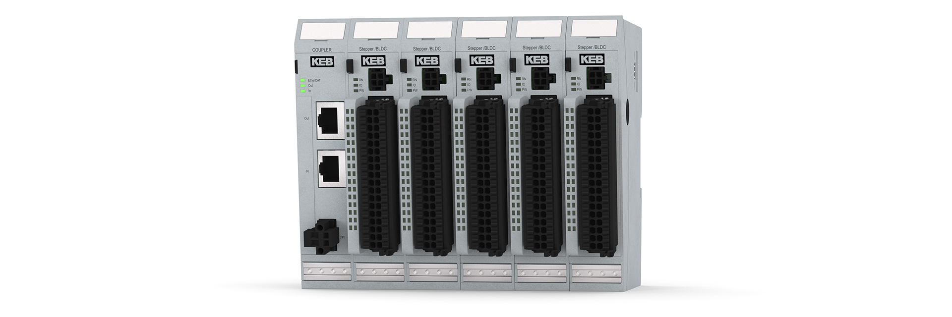
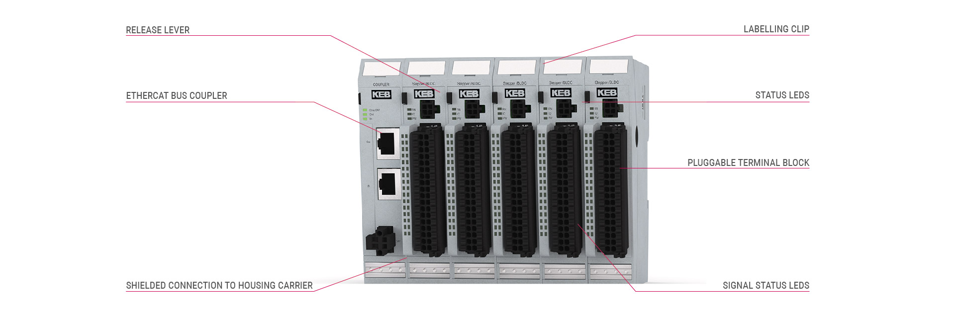
KEB’s C6 Remote I/O system offers various options for connecting process signals to an EtherCAT network. It is made up of a C6 Remote I/O bus coupler and additional I/O modules. The C6 Remote I/O bus coupler converts the physical transfer technology and generates the system voltages for the modules. In the process, the EtherCAT protocol is retained right through to the last I/O module. The modules each operate in the system as an independent EtherCAT slave. Like every EtherCAT slave, they can be configured individually as nodes. In addition, data is immediately available in the EtherCAT and does not need to be converted by a proprietary bus. At the end of the modular device, the connection between the forward and return lines is closed automatically, meaning that the next EtherCAT device can be plugged into the second bus coupler or extender port.
With a width of just 25 mm, the plug-in system has a high packing density. Thanks to the diverse module options and the continuity of the EtherCAT fieldbus, a wide variety of application-specific topologies can be implemented.
Highlights
- Complete EtherCAT I/O system in real time
- Compact construction (32DI on 25 mm)
- Extensive choice of I/O module types
- Plug-in terminals and modules
C6 I/O Modules
General technical data
Fieldbus | EtherCAT 100 Mbits/s |
---|---|
W x H x D | 25 x 120 x 90 mm |
Installation | 35 mm DIN Rail |
Controller | ET 1100 |
E-Bus connection | 10-in system plug in side wall |
End module | not necessary |
Power supply | 24 V DC (-20 % … +25 %) |
Potential separation | Modules to each other and to bus |
Operating temperature | 0 … +55 °C |
Storage temperature | -25 … +70 °C |
Relative humidity | 5 … 95 %, without condensation |
Protection class | IP 20 |
Resistance to interference | Zone B to EN 61131-2 |
Module specific technical Data
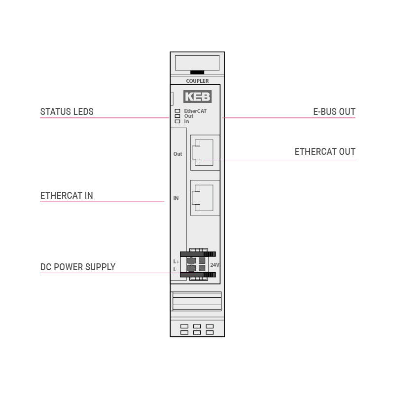
Bus Coupler
Fieldbus | EtherCAT 100 Mbits/s |
Power supply | 24 V DC (-20 % … +25 %) |
E-Bus supply | max. 3 A (approx. 20 modules) |
Cable length | max. 100 m between 2 bus couplers |
Connection | 2 x RJ45 |
Input current | 50 mA & E-Bus supply |
Fieldbus | EtherCAT 100 Mbits/s |
Power supply | 24 V DC (-20 % … +25 %) |
Supply E-Bus | max. 2 A (approx. 11 modules) |
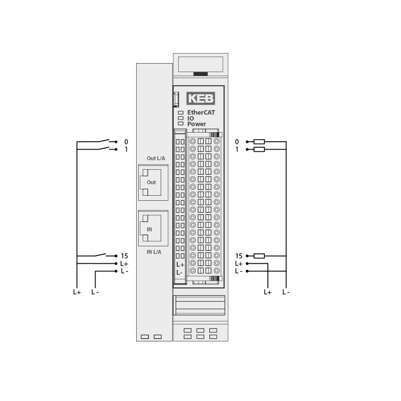
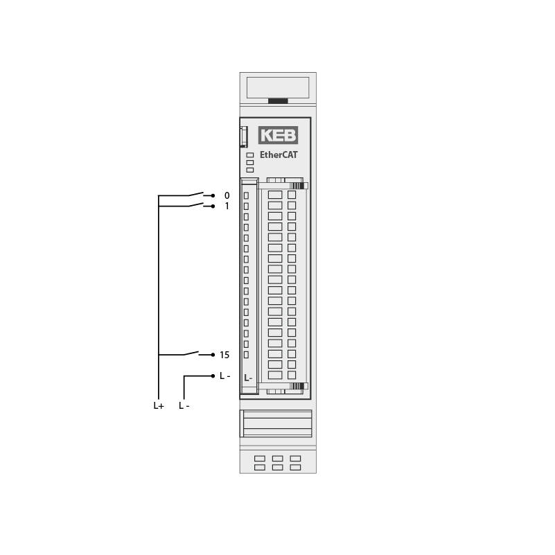
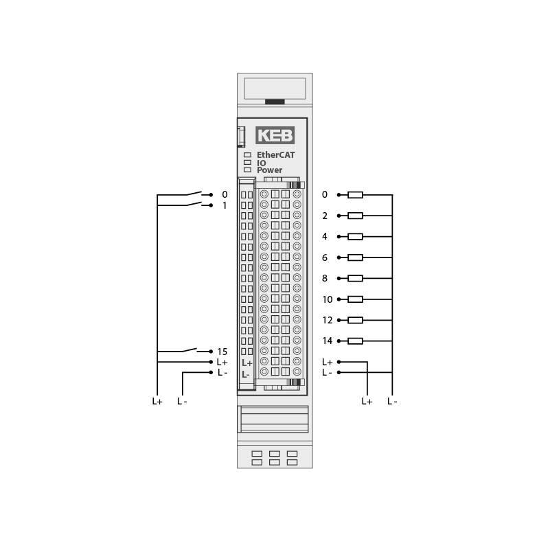
Digital Inputs | 16 |
Input delay | 3 ms |
Signal level | off -3 … 5 V on 15 … 30 V |
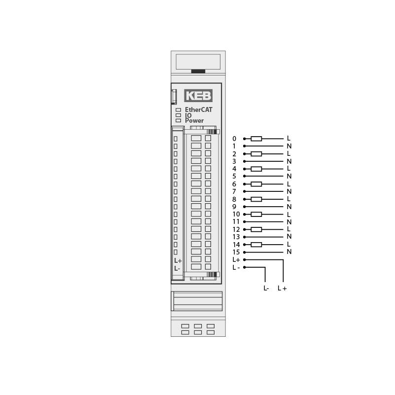
Digital outputs | 16 |
Max. current | 0.5 A per output |
Total current | max. 8 A |
E-Bus load | 135 mA |
Digital in-/outputs
Digital inputs | 16 |
Input delay | 1 ms |
Signal level | off -3 … 5 V on 15 … 30 V |
Digital outputs | – |
Max. current | – |
Total current | – |
E-Bus load | 100 mA |
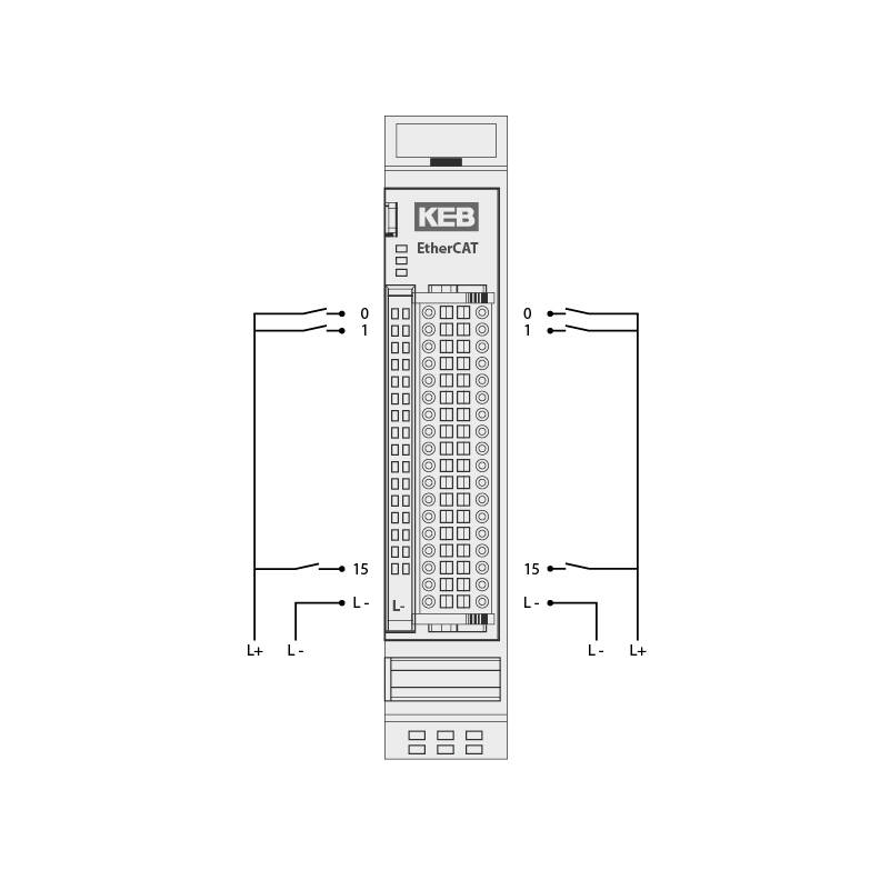
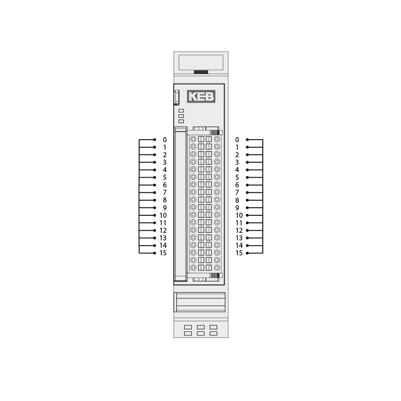
Digital inputs | 32 |
Digital delay | 1 ms |
Signal level | off -3 … 5 V on 15 … 30 V |
Digital outputs | – |
Max. current | – |
Total current | – |
E-Bus load | 85 mA |
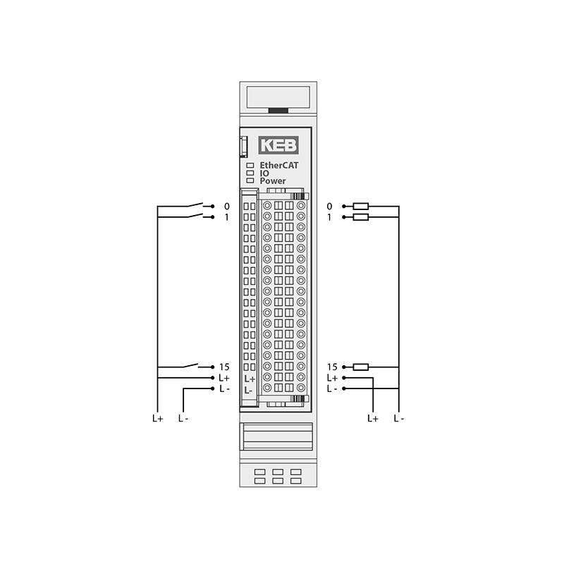
Digital inputs | 16 |
Input delay | 1 ms |
Signal level | off -3 … 5 V on 15 … 30 V |
Digital outpus | 16 |
Max. current | 0.5 A per output |
Total current | max. 8 A |
E-Bus load | 135 mA |
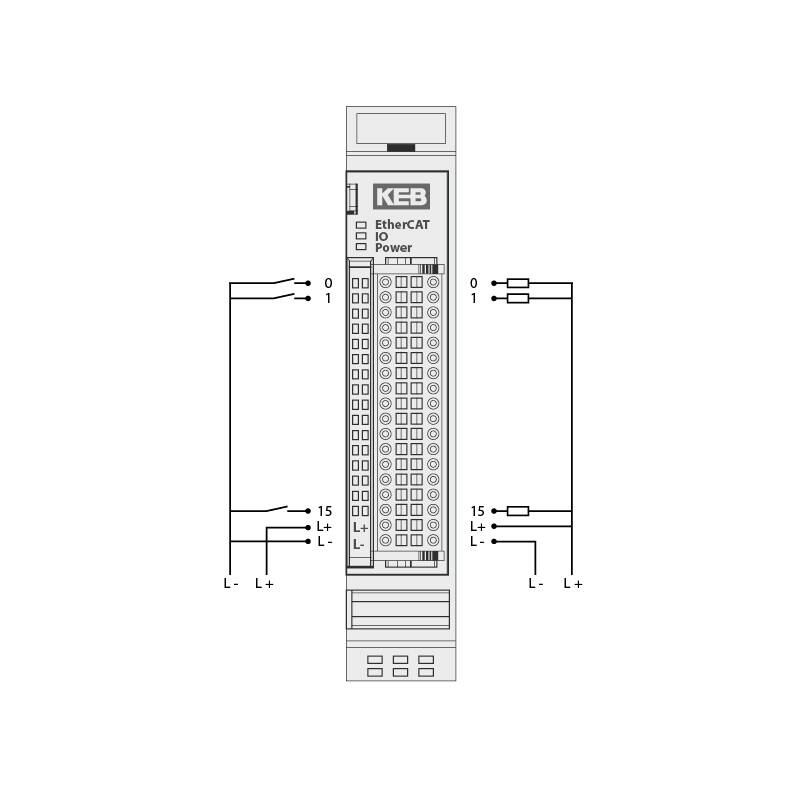
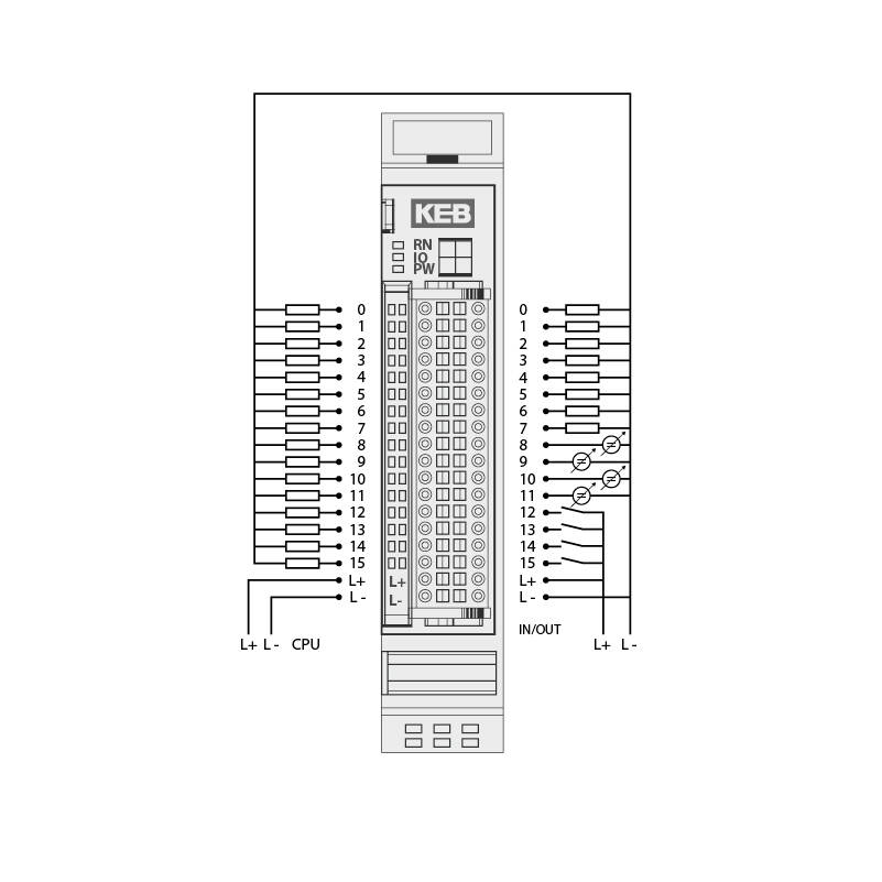
Digital Inputs | 16 |
Input delay | 1 ms |
Signal level | off 15 … 30 V on -3 … 5 V |
Digital outputs | 16 |
Max. current | 0.5 A per output |
Total current | max. 8 A |
E-Bus load | 135 mA |
Digital inputs | 16 |
Input delay | 1 ms |
Signal level | off -3 … 5 V on 15 … 30 V |
Digital outputs | 8 |
Max. current | 1 A per output |
Total current | max. 8 A |
E-Bus load | 135 mA |
Digital inputs | – |
Input delay | – |
Signal level | – |
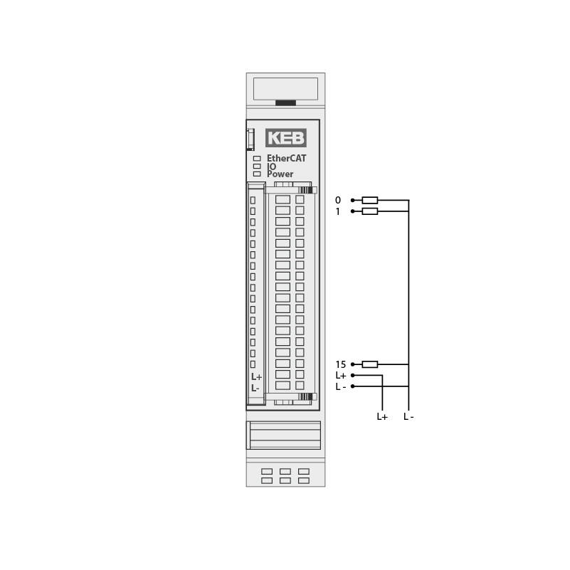
Digital outputs | 16 |
Max. current | 0.5 A per output |
Total load | max. 8 A |
E-Bus load | 130 mA |
Digital inputs | – |
Input delay | – |
Signal level | – |
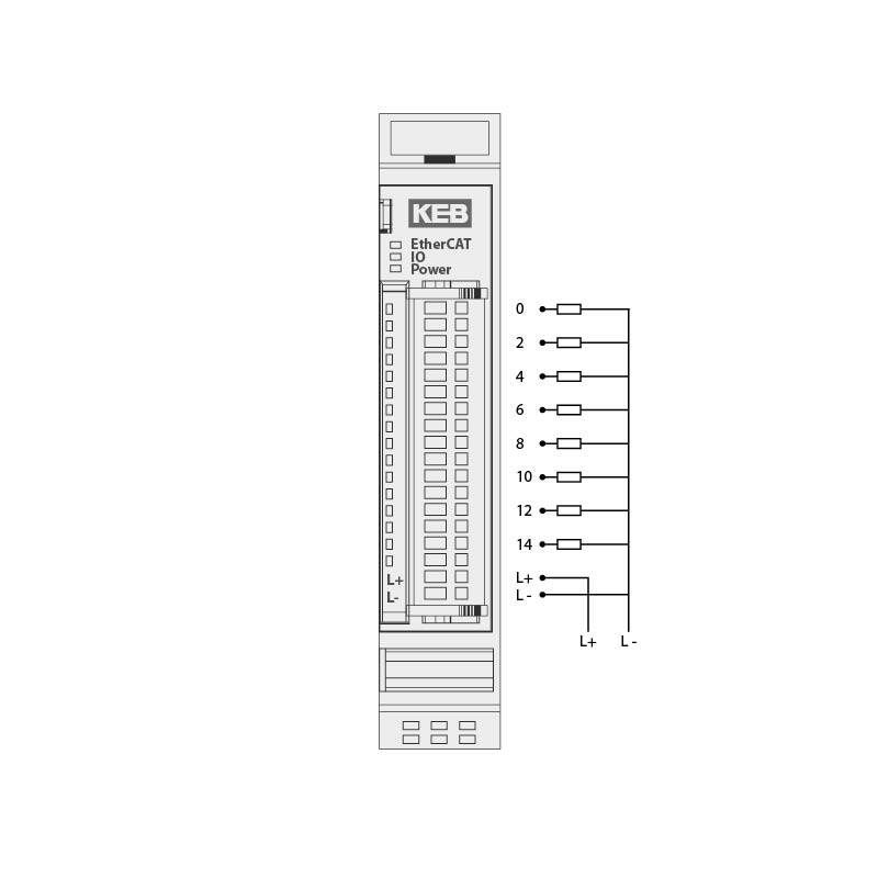
Digital outputs | 8 |
Max. current | 1 A per output |
Total current | max. 8 A |
E-Bus load | 130 mA |
Digital inputs | – |
Input delay | – |
Signal level | – |
Digitale outputs | 8 |
Max. current | 2 A per output |
Total current | max. 10 A |
E-Bus load | 130 mA |
Digital inputs | – |
Input delay | – |
Signal level | – |
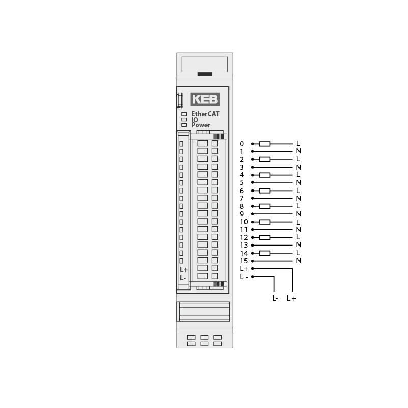
Digital outputs | 8 |
Max. current | 5 A (resistive) / 2 A (inductiv) |
Switching voltage | max. 24 V DC / 230 V AC |
Switching cycles mech. (min.) | 2 x 10 7 |
Switching cycles elec. (min.) | 3 x 10 5 (2 A / 30 V DC) |
E-Bus load | 130 mA |
Digital inputs | – |
Input delay | – |
Signal level | – |
Digital outputs | 8 |
Max. current | 5 A (resistive) / 2 A (inductiv) |
Switching voltage | max. 24 V DC / 24 V AC |
Switching cycles mech. (min.) | 2 x 10 7 |
Switching cycles elec. (min.) | 3 x 10 5 (2 A / 30 V DC) |
E-Bus load | 130 mA |
Counter / Fast inputs
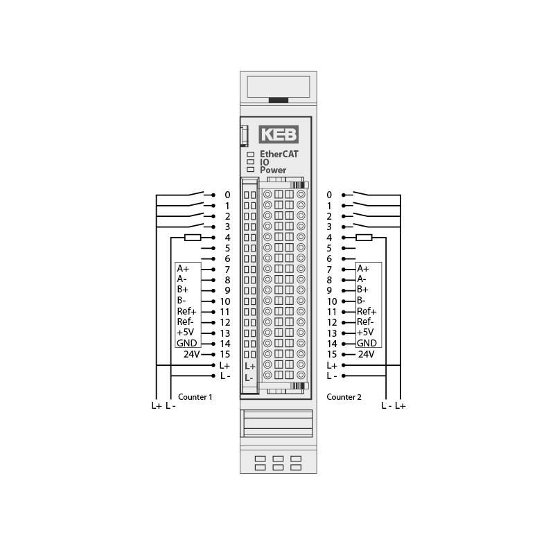
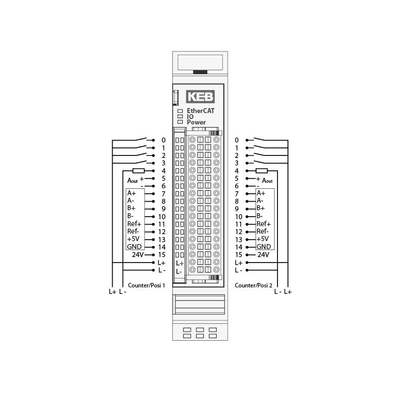
Encoder | 2 x A, B, Ref |
Encoder type | 5 V (RS422) |
Count frequency | max. 200 kHz |
Digital inputs | 8 |
Input delay | 1 ms |
Signal level | off -3 … 5 V on 15 … 30 V |
Digital outps | 2 |
Max. current | 2 A per output |
Analog outputs | – |
Resolution | – |
E-Bus-Last | 300 mA |
Encoder | 2 A, B, Ref |
Encoder type | 5 V (RS422) |
Count frequency | max. 200 kHz |
Digital inputs | 0 … +55 °C |
Input delay | -25 … +70 °C |
Signal level | 5 … 95 %, ohne Betauung |
Digital outputs | max. 3 A (approx. 20 modules) |
Max. current | 2 A per output |
Analog outputs | 2 |
Resolution | 12 bit |
E-Bus load | 300 mA |
Analog in-/outputs
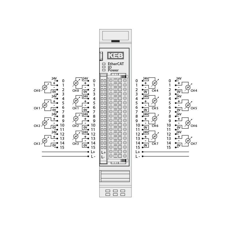
Analog inputs | 4 |
Resolution | 12 Bit (5,2 μA) |
Measurement range | 0 … 20 mA, 4 … 20 mA (end value 20 mA) |
Conversion time | 235 µs (if all channels are active) |
Output rate | – |
E-Bus load | 190 mA |
Analog inputs | 8 |
Resolution | 12 Bit (5,2 μA) |
Measurement range | 0 . . . 20 mA, 4 … 20 mA (end value 20 mA) |
Conversion time | 290 μs (if all channels are active) |
Output rate | – |
E-Bus load | 190 mA |
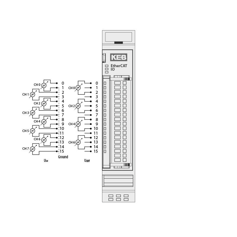
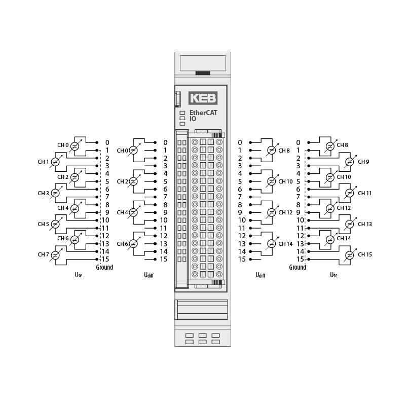
Analog inputs | 8 single-ended or 4 differential |
Resolution | 13 Bit (1.221 μV unipolar/ 2.422 μV bipolar) |
Measurement range | 0 … 10 V, ±10 V |
Conversion time | 464 μs (if all channels are active) |
Output rate | – |
E-Bus load | 190 mA |
Analog inputs | 6 single ended or 8 differential |
Resolution | 13 Bit (1.221 μV unipolar/ 2.422 μV bipolar) |
Measurement range | 0 … 10 V, ±10 V |
Conversion time | 580 μs (if all channels are active) |
Output rate | – |
E-Bus load | 190 mA |
Analog inputs | 4 |
Resolution | 16 Bit |
Measurement range | 0 … 10 V, ±10 V, 0 … 20 mA |
Output rate | 220 ms |
E-Bus load | 150 mA |
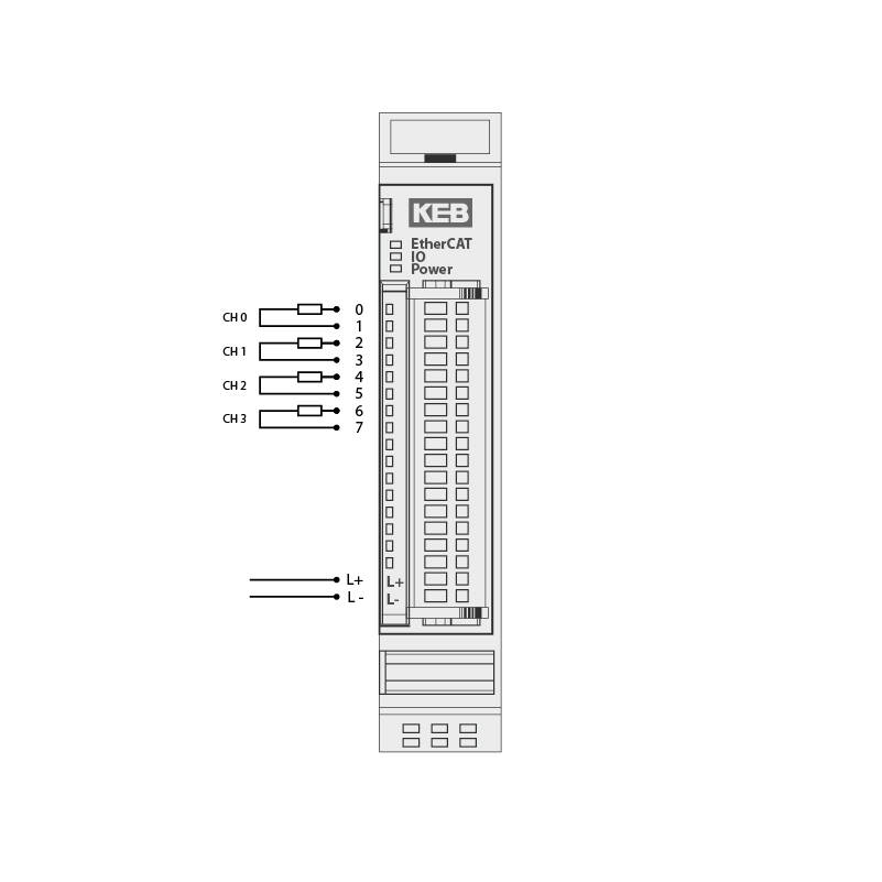
Analog inputs | 4 |
Resolution | 16 Bit |
Conversion time | 50 ms (adjustable) |
E-Bus load | 170 mA |
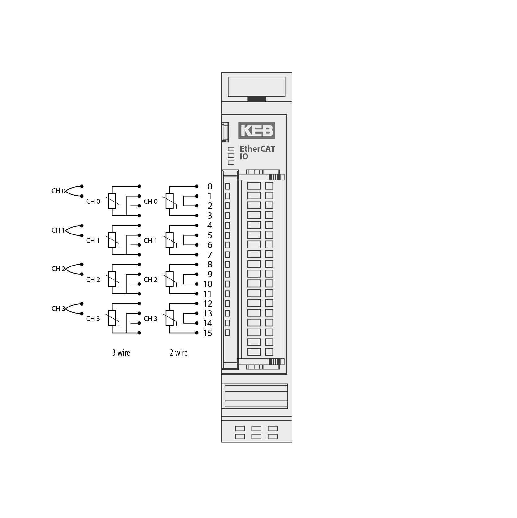
Thermoelement
Sensor types | J, K, mV (internal) |
Cold point compensation | yes |
Measuring range type K | -200 °C … +1372 °C |
Measuring range type J | -50 °C … +760 °C |
Measuring range mV | -40 … +65 mV |
Pt100 / Ni100
Measuring range Pt | -75 °C … +670 °C |
Measuring range Ni | -60 °Cv+250 °C |
Input resistance | 70 … 320 Ω |
Measuring current | 1 mA (typical) |
Pt1000 / Ni1000
Measuring range Pt | -75 °C … +670 °C |
Measuring range Ni | -60 °C … +250 °C |
Input resistance | 700 … 3200 Ω |
Measuring current | 0,1 mA (typical) |
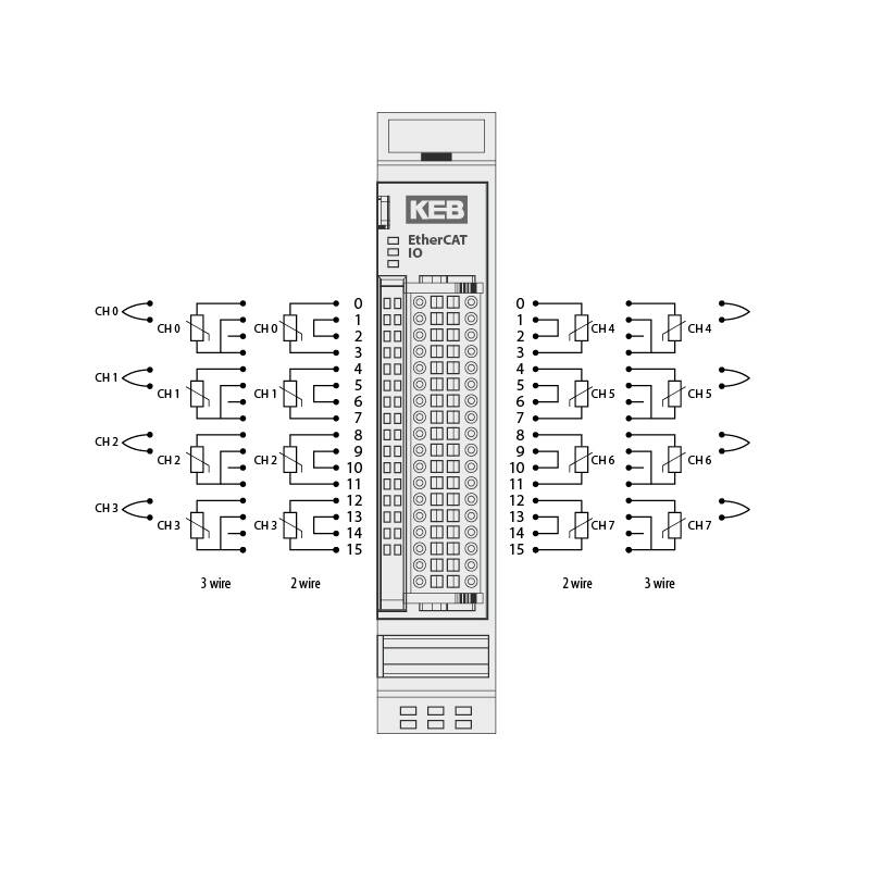
Analog inputs | 8 |
Resolution | 16 Bit |
Conversion time | 50 ms (einstellbar) |
E-Bus load | 170 mA |
Thermocouple
Sensor types | J, K, mV (internal) |
Cold point compensation | yes |
Measuring range type K | -200 °C … +1372 °C |
Measuring range type J | -50 °C … +760 °C |
Measuring range mV | -40 … +65 mV |
Pt100 / Ni100
Measuring range Pt | -75 °C … +670 °C |
Measuring range Ni | -60 °C … +250 °C |
Input resistance | 70 … 320 Ω |
Measuring current | 1 mA (typical) |
Pt1000 / Ni1000
Measuring range Pt | -75 °C … +670 °C |
Measuring range Ni | -60 °C … +250 °C |
Input resistance | 700 … 3200 Ω |
Measuring current | 0,1 mA (typical) |
Fieldbus extension
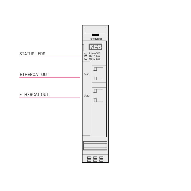
Fieldbus options | 2x EtherCAT 100 Mbits/s |
Power supply | via E-Bus |
E-Bus load | 160 mA for OUT1 210 mA for OUT1 + OUT2 |
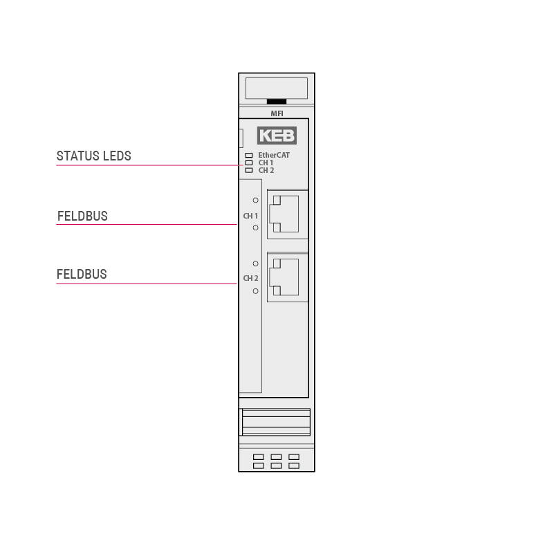
Fieldbus options | PROFINET Slave |
Power supply | via E-Bus |
E-Bus load | 240 mA |
Prozess data | max. 384 Byte |
Fieldbus options | EtherCAT Slave |
Power supply | via E-Bus |
E-Bus load | 240 mA |
Prozess data | max. 384 Byte |
Fieldbus options | EtherNET IP Slave |
Power supply | via E-Bus |
E-Bus load | 240 mA |
Prozess data | max. 384 Byte |
Fieldbus options | POWERLINK Slave |
Power supply | via E-Bus |
E-Bus load | 240 mA |
Prozess data | max. 384 Byte |
I/O Drive Controller
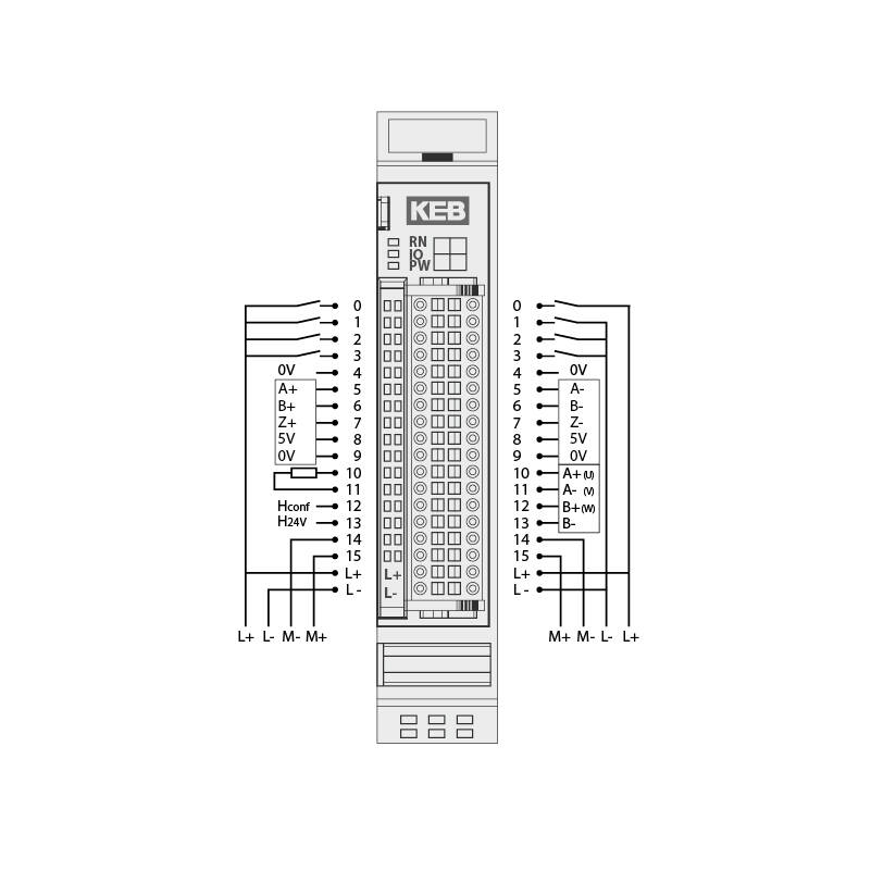
Motor connection | 2-phase stepper motor or brushless DC motor |
Motor voltage | 12 V … 72 V DC / cULus: 12 V … 42 V DC |
Motor current nominal | 5 A |
Peak current | Stepper motor: 10 A / brushless DC Motor: 15 A |
Incremental emitter | 5 V / 24 V (A, /A, B, /B, Z, /Z) |
Hall emitter | 5 V / 24 V (H1, H2, H3) or 3 extra zero-switching digital inputs |
Digital inputs | 5 x 1 ms configurable, e.g. reference switch, limit switch, release |
Digital outputs | 1 x 0.5 A (brake output or standard output) |
Control | CIA402 |
E-Bus load | 100 mA |
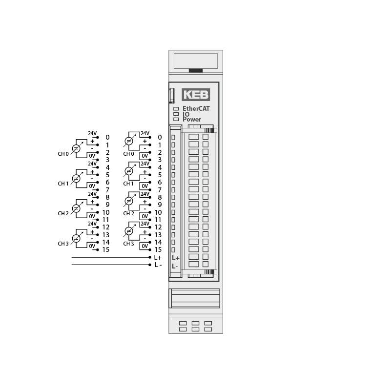
Mixed I/O
Digital inputs | 4 (8) |
DI0..3 | 1 ms |
DI4 | 0.1 ms |
DI5 … 7 | 0.001 ms |
Counter (DI5) | 500 kHz (up to 1 MHz) |
Digital outputs | 24 |
DO0 … 7 | 0.5 A |
DO8 … 23 | 0.1 A |
Analog inputs 12 Bit | 4 x 0 … 10 V (also useable as DI, DI0 … 3) |
Sampling rate | 1 ms |
RS485 | potential-separated |
Baud rate | 2.4 … 921.6 kBit/s |
E-Bus load | 90 mA |
Accessories
Connections | 2 x 16 |
The module has 2 separate potential lines | |
E-Bus load | 0 mA |
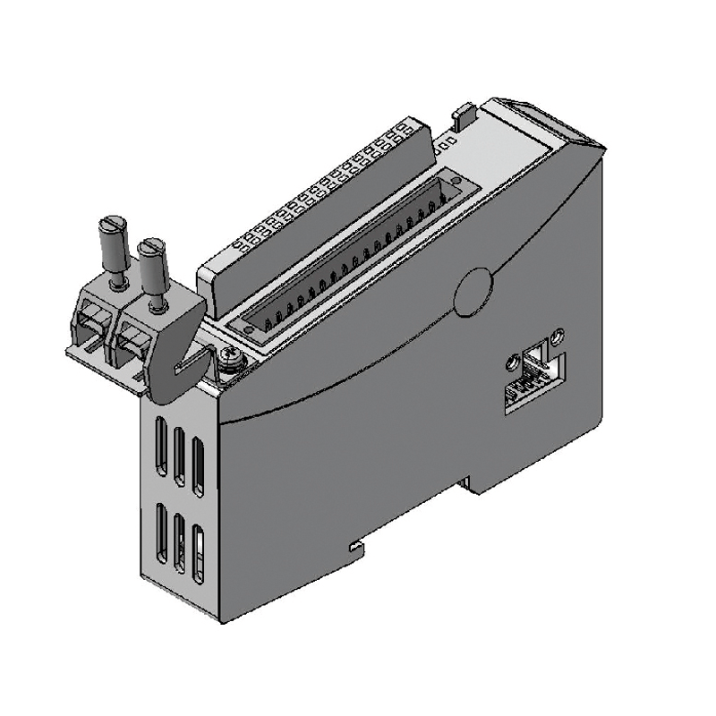
KEB IO EtherCat connection terminal 2 x 8 mm
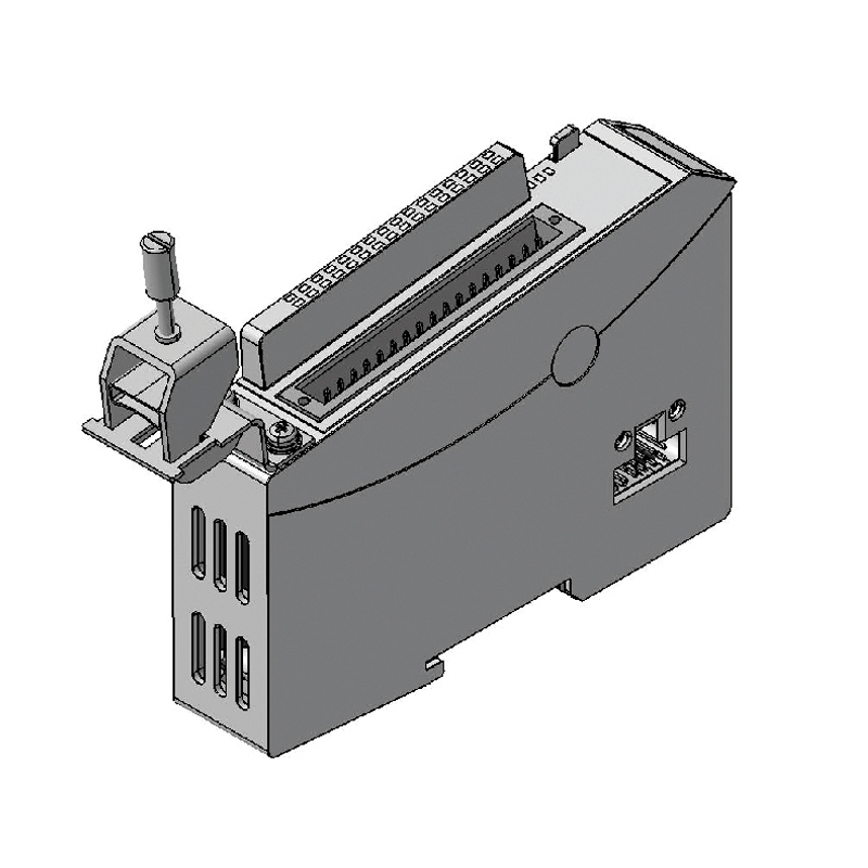
KEB IO EtherCat connection terminal 14 mm